Glass Inspection
In so many of today’s markets, advancing technologies require quality and cleanliness levels pushing existing capabilities. At Coresix, we are continually improving our cleaning and inspection processes to establish ever higher standards of excellence. With multiple advanced ultrasonic cleaning systems feeding directly into a Class 100 Optical Clean Room, inspection conditions are established to exceed product specifications, thereby assuring that the quality of parts received will exceed the customer’s expectations.
Optical Clean Room
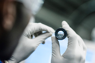
Our optical clean room is a completely darkened environment for maximum effectiveness of the inspection lighting and is certified as Class 100. All cleanliness and surface quality critical components are inspected and packaged within the clean room.
LEARN MORE
Class 100 Optical Clean Room
At Coresix, cleanliness is treated as an independent technology, procedures for which are continuously monitored and improved upon. With many of today’s technologies, the introduction of foreign matter to the process can have a serious impact on production yields and product performance. Coresix provides a unique niche in our ability to clean glass and maintain the highest level of cleanliness to the customer’s door.
Cleanrooms are classified according to the number and size of particles permitted per volume of air. Large numbers like "class 100" or "class 1000" refer to FED-STD-209E, and denote the number of particles of size 0.5 µm or larger permitted per cubic foot of air.
A class 100 cleanroom maintains less than one hundred particles larger than 0.5 microns in each cubic foot of air space.
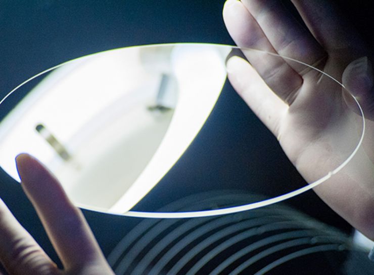
Light Conditions
When inspecting glass components, Coresix establishes a light condition corresponding to the physical specification. By establishing the appropriate light condition, inspection position, and inspection time, visible inspection is simplified to “no visible defects” thereby eliminating operator judgement. These conditions are always set to exceed the established cosmetic quality, thereby always exceeding the customer’s expectations.
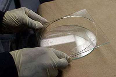
Flatness
The improved optical flatness of a glass component is achieved through the lapping process. By conditioning the lapping plates and monitoring variables on the lapping machines, the top and bottom surfaces of the glass part are ground parallel in an extremely controlled process. Depending on the material and thickness, Coresix can generally produce a quarter-wave flatness.
LEARN MORE
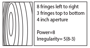
Power & Irregularity
This is a common way of interpreting the results of an interferometer as described the the "fringes" definition above. Counting the fringes from left to right, then top to bottom, the larger number is the "power". Subtract the smaller number from the larger number to get the irregularity. The final number being the size of the aperture, the spec then reads P/I/A. For the example below, the flatness is 8/5/4 (8 fringes power, 5 fringes. As expressed over a defined aperture (ex. 12/12/4 = 12 fringes of power and 12 fringes of irregularity over a four-inch aperture) is measured in newton rings on an interferometer.
Wavelength
The distance between repeating units of a wave pattern. Another way of expressing flatness is defined by the number of Newton rings measured over a given area. (1 wave = 2 fringes)
Arc Minutes and Seconds
Parallelism of top of one surface to another in degrees (1 arc min = 1' = 1/60 deg, 1 arc sec = 1" = 1/60 arc min)
Lambda (λ)
The Greek letter is commonly used to designate wavelength.
Stigmatism
Irregularities within the glass cause an interruption to the transmitted flow of light through the glass.
Fringes
Measured by the interferometer, a fringe is a distortion in the surface relative to an optical plane (1 fringe = ½ wave)Using an interferometer with a monochromatic light source, the object part is measured against an optical flat. As light reflects in the gap between the object and the optical flat, the light will interfere with itself creating light and dark fringes or bands. As commonly measured on a helium-neon laser at a wavelength of 632.8nm, each fringe is equal to .316 microns. These fringes can be counted to express flatness over a given area or evaluated as a contour map and interpreted for shape and flatness.
Fringes (Power and Irregularity)
Microns
A common way of expressing flatness is a peak to valley measurement in microns, either within a specified area or across the entire part. Defines flatness in peak to valley measurement over a given area.
TIR
"Total Indicator Reading" is the maximum focal plane deviation relative to a known reference plane.
P-V TIR

Bow or Warp
A curve, bend, or other deviation from flatness.
Saddle
A negative curvature or irregularity in the glass surface produces a saddle shape.

Scratch and Dig
A scratch and dig spec can be written and an inspection standard developed around any known requirements. The sample specifications listed below are intended to provide a general guideline and encompass the most commonly used values.
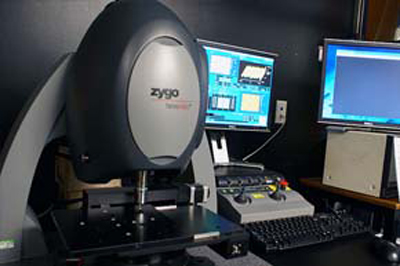
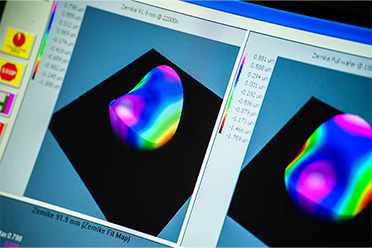
Metrology
At Coresix, we continually invest in the metrology equipment necessary to verify and advance our process results. Metrology Equipment Used At Coresix Measures flatness, line profile, radius, and other surface parameters to the accuracy of 50nm Zygo.